Introduction:
if this iterm can not meet your needs
our products have 1 Year Warranty to ensure the quality
Before you place the order
make sure it fits your vehicle
we hope you enjoy your shopping
Fit For:
1999 - 2004 HONDA ODYSSEY All Models
Package Includes:
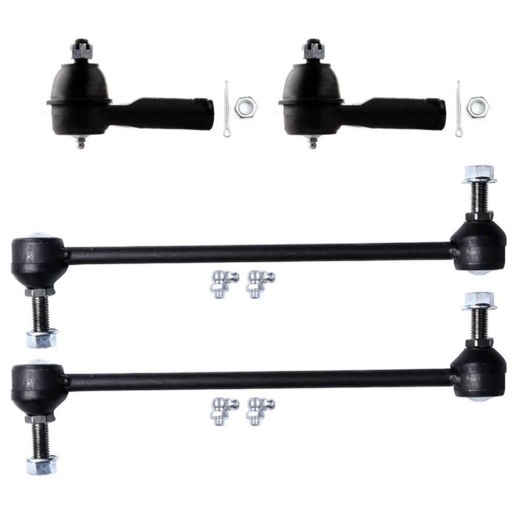
2x Front Outer Tie Rod Ends - ES3669
2x Front Sway Bar End Links - K90349
Note:
Some of the parts we have grease fittings and other parts come factory sealed
you may receive 1 of the parts.but don\'t worry
this does not affect the performance or quality of the parts
Tie-Rod End
Outer Tie-Rod End
Inner Tie-Rod End
Some inner tie-rod ends contain a bolt and bushing. These tie-rod ends are threaded onto the rack. Since the rack is connected directly to the tie-rods, the rack replaces the center link in a parallelogram steering linkage
Some inner tie-rod ends have a mirror-finished ball and a high-strength polymer bearing to ensure low torque, minimal friction, and extended life. A hardened alloy steel rod extends from the ball to the outer tie-rod end and provides maximum strength and durability
Tie-Rod End Replacement Guideline:
This useful tip applies to the exchange of tie rod ends and inner tie rods, which together form the so-called tie rod
Note: Cleanliness is extremely important when working on the power steering. Incorrect work and contamination can lead to leakage and, in the worst case, to failure of the steering assistance
1.Lift the vehicle and dismount the front axle wheels
2.Spray the fastening nut of the tie rod end with rust remover and leave it on for a few minutes
3.Dismount the front underride guard
4.Loosen the fastening nut from the tie rod and remove it completely
5.Remove the tie rod end from the steeringknuckle using an appropriate ball joint separator
6.Remove the clamp of the bellow on the steering gear
7.Push the bellow towards the tie rod end
8.Unscrew the inner tie rod from the rack
9.Clean the sealing face of the bellow at the steering gear
10.Clean the lug of the rubber contact surface of the ball joint in the steering knuckle
Note:Always use new self-locking nuts and bolts for a reliable repair
11.Screw the new inner tie rod into the rack and tighten it with the tightening torque that has been specified by the vehicle manufacturer
12.Mount the bellow and close the clamps with the appropriate special tool
Note:Incorrect mounting of the bellow can lead to corrosion of the rack: the steering gear starts leaking which can lead to a failure in the steering assistance
13.Secure the ball joint in the steering knuckle and mount the nut. Please observe the tightening torque suggested by the vehicle manufacturer
Note:During mounting, the ball stud should not turn within the ball joint. This can cause damage inside the ball joint and can lead to early failure
Tip:Secure the ball stud against twisting with a suitable tool
14.Mount the front underride guard
15.Mount the front wheels and tighten them with the tightening torque recommended by the vehicle manufacturer
16.Align the wheels and adjust them if necessary. Observe the vehicle manufacturer specifications
17.Perform a test drive
Sway Bar
Some control arm bushings can be replaced with the arm still on the vehicle; others require removal of the arm. On a few applications, control arm bushings are threaded into the control arm, but most are press fitted
Press fitted bushings can be removed and installed with a bushing driver. Some may be removed with an air chisel, and some may be pressed into the arm with the retaining nut. This method can require periodic vibration of the control arm to coax the bushing into place
Care must be used in bushing replacement to avoid damage to the control arm. To properly position the bushing, the weight of the vehicle must be on the suspension before tightening the nut on most designs. Check the service information for the vehicle for the proper procedure
Replacement of other types of suspension bushings is generally straightforward. Consult the service information
Sway Bar Stabilizer Link Replacement Guideline:
While driving, the following signs may indicate a faulty sway bar stabilizer link:
(1).Rattling and thumping noises on rough roads
(3).Stronger inclination of the vehicle during cornering
If the sway bar stabilizer link is found to be defective, it should be replaced as described below
1.Raise vehicle and remove front wheels
Tip:Always check both stabilizer links and replace them in pairs if necessary
2.Spray fastening nuts of the stabilizer link with rust remover and let act for a few minutes
3.Loosen the lower fastening nut of the stabilizer link at the stabilizer and remove
Tip:If the ball stud also starts to turn, hold it with a suitable tool
4.Press stabilizer link out of torsion bar
5.Loosen the upper fastening nut of the stabilizer link at the suspension strut and remove it
6.Press stabilizer link at suspension strut out of bracket
7.Insert new stabilizer link at suspension strut
8.Tighten stabilizer link at suspension strut to the tightening torque specified by the vehicle manufacturer
9.Insert new stabilizer link at stabilizer
10.Tighten stabilizer link at stabilizer to the tightening torque specified by the vehicle manufacturer
11.Remount the front wheels. Lower the vehicle and tighten the wheel studs to the tightening torque specified by the vehicle manufacturer
Tip:Even if replacing the stabilizer link does not directly affect the chassis setting, we recommend checking the axle setting and adjusting if necessary after working on the suspension
12.Conclude with a test drive
Frequently Asked Questions
(1).When to replace tie rod ends?
(2).Why should I get my tie rods inspected on a regular basis?
(3).Vibrations
(4).Shaking
(5).Wandering
(6).What is sway bar?
(7).What are the symptoms of a bad sway bar?
(8).What happens when a stabilizer bar breaks?
(9).What is the most important tip to offer to help with anti-sway bar installation?
The most important thing is to ensure is that your wheels are not hanging. The suspension should be compressed so the control arms, etc. are at the same position they would be if the vehicle were sitting at ride height. This can be done by using ramps, a drive on lift, or simply loading the wheels if the vehicle is on jack stands or a two point lift. If this is not done the arc that the bar and suspension moves through due to the excessive travel can make things very difficult to line up
(10).How long will it take to replace the front sway bar?